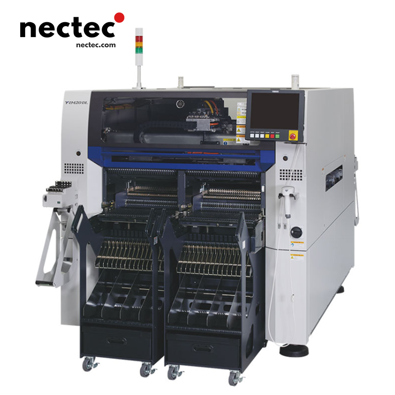
S10 | 3D Hybrid Universal Module Placement Machine
The S10 model has 3D placement capabilities. It can realize 3D placement with interactive solder paste dispensing and component placement through the newly developed interchangeable dispensing head; it can be expanded to 3D MID placement, and can operate on concave and convex, inclined and curved surfaces to meet the needs of automotive, medical, communication equipment and other fields. It can handle large and long substrates with a maximum size of L1,330 x W510mm (when the buffer function is not used), and can be accurately positioned by laser sensors to adapt to PCBs of different shapes and sizes. It also has a variety of component processing: it can handle components from 0201mm to 120 x 90mm, including BGA, CSP, connectors, etc.; the maximum component height is 30mm (including substrate thickness); the maximum feeder capacity is 90 types (converted to 8mm tape), and supports multiple feeding methods.
Its placement speed and accuracy have reached 0.08 seconds/CHIP (45,000CPH) under the best conditions for 12-axis 20-head unit, CHIP placement accuracy ±0.040mm, IC placement accuracy ±0.025mm, and placement angle ±180 degrees. Its equipment size is L1,250 x D1,750 x H1,420mm and weighs about 1,200kg. It also has negative pressure and image dual component return detection function and color reference mark recognition camera with new lighting unit to improve recognition accuracy; and supports multi-language operation interface. Its feeder compatibility is strong, and new and existing material change trolleys can be mixed and used.
S10 | 3D Hybrid Universal Module Placement Machine
- Description
Description
Placement Head System
12-Spindle, 20-Nozzle Multi-Axis Head
- High-Performance Placement Module: Achieves 45,000 CPH (0.08s/CHIP) under IPC-9850 conditions, with ±40μm (3σ) accuracy for CHIP components and ±25μm (3σ) for ICs. Supports 0201 metric (0.2×0.1mm) micro-components to 120×90mm odd-form devices (BGA, CSP, connectors) with ±180° rotational placement.
- Dynamic Axis Control: AC servo-driven Z-axis (0.1–50N force control) and θ-axis enable precise height adjustment (components up to 30mm tall) and polarity alignment, suitable for pressure-sensitive and through-hole components.
- Intelligent Nozzle Management:
- RFID-enabled nozzle ID recognition for automatic type verification.
- 24-station standard/40-station optional nozzle changers with free-form placement for rapid tooling changes.
- Optional dispense head integration enables hybrid 3D assembly (solder paste deposition + component placement).
Feeder System
Hybrid Feeding Infrastructure
- Multi-Modal Component Supply:
- F1/F2 series: 8–56mm pneumatic tape feeders
- F3 series: 8–88mm electric tape feeders
- Stick feeders and JEDEC-standard tray systems (sATS15R compatible)
- 90-Station High-Density Configuration (8mm tape equivalent): Reduces changeover frequency in high-mix production.
- Modular Feeder Carts: Supports mixed legacy/new trolleys (e.g., CFB-45E, CFB-36E) for flexible budgeting, with 45-track carts enabling batch feeder exchange.
PCB Handling System
Ultra-Flexible Substrate Management
- Substrate Compatibility:
- Standard: 50×30–1,330×510mm (955×510mm typical)
- Buffered: 420×510mm (inlet/outlet buffers)
- Thickness: 0.4–4.8mm, including routed/odd-shaped boards
- High-Velocity Conveyor: 900mm/sec transport with laser-guided auto-width adjustment (no mechanical stops), ensuring ±0.1mm fiducial alignment.
- Adaptive Clamping System: Front-reference positioning with vacuum clamping minimizes board shift during placement.
Vision & Inspection System
Advanced Quality Assurance Suite
- Pick-and-Place Verification:
- Negative pressure sensing + 2D/3D vision for real-time mispick detection (defect rate <0.02%).
- Color vision system with multi-spectrum lighting for fiducial recognition and solder paste inspection.
- Component Recognition Capability:
- Standard camera: 0402–120×90mm components; optional upgrade for 0201 metric.
- Rear multi-scan camera: Enhances odd-form component alignment efficiency.
- 3D MID (Molded Interconnect Device) Support: Enables multi-surface placement on concave/convex/inclined 3D structures for automotive/medical applications.
Motion Control System
Precision Motion Architecture
- Closed-Loop AC Servo Drives: X/Y axes with high-precision linear guides ensure sub-micron stability, supporting 0.4mm pitch components.
- Dynamic Vibration Damping: Active control reduces mechanical resonance during high-speed operation, maintaining placement consistency.
Auxiliary Systems
Global Production Readiness
- Multilingual HMI: Supports English, Chinese, Japanese, and Korean for cross-regional operability.
- Modular Line Configuration: Freely configurable front/rear feeder banks and trolley/rack systems, with retrofit kits for feeder type conversion.
- Additive Manufacturing Integration: Expanded 3D placement capabilities for MID components, enabling complex 3D assembly in advanced electronics.
specification
Model | S10 |
Board size(with buffer unused) | Min. L50 x W30mm to Max. L1,330 x W510mm (Standard L955) |
Board size(with input or output buffer used) | Min. L50 x W30mm to Max. L420 x W510mm |
Board size(with input and output buffers used) | Min. L50 x W30mm to Max. L330 x W510mm |
Board thickness | 0.4 – 4.8mm |
Board flow direction | Left to right (Std) |
Board transfer speed | Max 900mm/sec |
Placement speed (12 heads + 2 theta) Opt. Cond. | 0.08sec/CHIP (45,000CPH) |
Placement accuracy A (+3) | CHIP +/-0.040mm |
Placement accuracy B (+3) | IC +/-0.025mm |
Placement angle | +/-180 degrees |
Z axis control / Theta axis control | AC servo motor |
Component height | Max 30mm*1 (Pre-placed components: max 25mm) |
Applicable components | 0201 (mm) – 120x90mm, BGA, CSP, connector, etc. (Standard 01005 -) |
Component package | 8 – 56mm tape (F1/F2 Feeders), 8 – 88mm tape (F3 Electric Feeders), stick, tray |
Drawback check | Vacuum check and vision check |
Screen language | English, Chinese, Korean, Japanese |
Board positioning | Board grip unit, front reference, auto conveyor width adjustment |
Component types | Max 90 types (8mm tape), 45 lanes x 2 |
Transfer height | 900 +/- 20mm |
Machine dimensions, weight | L1250xD1750xH1420mm, Approx. 1,200kg |
Related Products