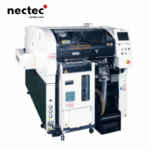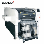

NPM-W2 | Modular Chip Mounter
The NPM-W2 amplifies the original NPM-W capabilities with a 10% throughput boost and 25% more accuracy. It also integrates new innovations like our incomparable Multi Recognition Camera. Combined, these features extend the component range down to the 03015mm microchip, yet preserve capability up to 120x90mm components up to 40mm tall and nearly 6” long (150mm) connectors. Featuring a revolutionary Multi Recognition Camera that uniquely combines three separate imaging capabilities into a single system: 2D alignment, component thickness inspection, and 3D coplanarity measurement.

NPM-W2 | Modular Chip Mounter
- Description
Description
Placement Head System
8-Nozzle Multi-Configuration Head
- Versatile Placement Module: Designed for high-volume standard component placement, achieving 18,000 CPH (0.20s/component) in PC format and 17,460 CPH (0.21s/component) in M format. Provides ±40μm placement accuracy (Cpk≥1.0) for general-purpose components like 0603 chips.
- 3-Nozzle V2 Precision Head: Features 100N maximum placement force for odd-form components (e.g., connectors, large ICs). Achieves ±30μm accuracy (Cpk≥1.0) for QFP packages, handling components from 0603 to 150×25×30mm (L×W×H).
Vision Inspection System
Integrated Multi-Sensor Vision Module
- 3D Component Metrology: Combines high-speed component alignment, Z-axis height measurement, and coplanarity inspection in a single pass. Enables stable recognition of micro-components (0201) and complex odd-form parts with sub-50μm precision.
- Adaptive Imaging Technology: Optimizes contrast for diverse component types (e.g., reflective metal terminals, matte plastic bodies) to ensure placement accuracy and first-pass yield.
Feeding System
Hybrid Component Supply Ecosystem
- Multi-Modal Feeding Capability:
- Tape Feeding: Supports 4–104mm tape widths (4/8/12/16/24/32/44/56/72/88/104mm).
- Tray Feeding: Front/rear tray units accommodate up to 40 trays (20 per side).
- Stick Feeding: Supports 12 single-stick feeders (front/rear) or 28 stick feeders via cart.
- Modular Feeder Configuration: Quick reconfiguration via tray unit rearrangement or feeder cart exchange, enabling ≤5-minute changeovers for mixed-component production.
- Batch Feeder Cart System: Enables rapid product changeovers by pre-loading feeders offline, reducing downtime in high-mix environments.
PCB Handling System
Dual-Lane/Single-Lane Flexibility
- Single-Lane Mode:
- PC format: 50×50–510×590mm
- M format: 50×50–510×510mm
- Dual-Lane Mode:
- PC format: 50×50–510×300mm (dual-track)
- M format: 50×50–510×260mm (dual-track)
- Seamless Board Changeover:
- Dual-lane: Theoretically 0-second changeover (for cycle times ≤4.0s).
- Single-lane: 4.0-second changeover for single-sided PCBs.
Auxiliary Systems
Automated Production Continuity
- Intelligent Material Handling: Integration with automated storage systems (AS/RS) enables non-stop production via offline feeder setup and parallel changeover.
- Predictive Maintenance Suite:
- Auto-replaceable support pins reduce manual adjustment errors.
- IoT-enabled diagnostics monitor feeder/nozzle wear, sending maintenance alerts via cloud connectivity (optional).
- Flexible Line Configuration: Supports quick switching between tape/tray/stick feeding and multi-head setups, optimizing OEE for small-batch, high-variety production.
Key Terminology Upgrades:
- Placement:
- “Multi-configuration head” replaces “highly versatile”.
- “Odd-form components” standardized for non-rectangular parts.
- Vision:
- “3D metrology” emphasizes precision measurement capabilities.
- “First-pass yield” quantifies quality performance.
- Feeding:
- “Hybrid ecosystem” highlights mixed-supply flexibility.
- “Modular configuration” for quick feeder reconfiguration.
- PCB Handling:
- “Seamless changeover” for zero-delay transitions.
- “Dual-lane” clarified over “dual-track”.
- Maintenance:
- “IoT-enabled diagnostics” for smart factory integration.
- “OEE optimization” links to overall equipment effectiveness.
specification
Model ID | NPM-W2 | ||||||||||
Front head Rear head | Lightweight 16-nozzle head V3A | 12-nozzle head | Lightweight 8-nozzle head | 3-nozzle head V2 | Dispensing head | No head | |||||
Lightweight 16-nozzle head V3A 12-nozzle head | NM-EJM7D | NM-EJM7D-MD | NM-EJM7D | ||||||||
Lightweight 8-nozzle head | |||||||||||
3-nozzle head V2 | |||||||||||
Dispensing head | NM-EJM7D-MD | NM-EJM7D-D | |||||||||
Inspection head | NM-EJM7D-MA | NM-EJM7D-A | |||||||||
No head | NM-EJM7D | NM-EJM7D-D | |||||||||
PCB dimensions | Single-lane1 | Batch mounting | L 50 mm X W50 mm to L 750 mm X W 550 mm | 2-positin mounting | L 50 mmxW50 mm to L 350 mmXW550 mm | ||||||
Dual-lane·1 | Dual transfer(Batch) | L 50 mm xW50 mm to L750mm XW260 mm | Dual transfer(2-positin) | L 50 mm xW50 mm to L350 mm xW260 mm | |||||||
Single transfer(Batch) | L 50 mm xW50 mm to L750 mm x W510 mm | Single transfer(2-positin) | L 50 mm X W50 mm to L 350 mmX W 510 mm | |||||||||
Electric source | 3-phase AC 200,220,380,400,420,480V 2.8 kVA | ||||||||||
Pneumatic source · | 0.5 MPa、200L/min(A.N.R.) | ||||||||||
Dimensions· | W1 280mmX D 2 465mmxH1 444mm /W 1 280 mmx D 2323 mmx H 1 444 mm *5 | ||||||||||
Mass | 2 850 kg** | / 2 780 kg *5 | |||||||||
Placement head | Lightweight 16-nozzle head V3A ( Per head) | 12-nozzle head ( Per head) | Lightweight 8-nozzle head ( Per head ) | 3-nozzle head V2 ( Per head ) | |||||||
High production mode [ON] | High production mode [OFF] | High production mode [ON] | High production mode [OFF] | ||||||||
Placement speed *at optimum conditions | 42 000 cph(0.086s/chip | 35 000 cph (0.103 s/chip) | 32 250 cph (0.112s/chip) | 31 250 cph(0.115s/chip) | 20 800 cph(0.173 s / chip) | 8 320 cph (0.433 s / chip) 6 500 cph(0.554 s /QFP) | |||||
Placement accuracy (Cpk≥1) *at optimum conditions | ±40 μm/ chip | ±30μm/ chip (±25μm/chips) | ±40 μm/ chip | ±30μm/ chip | ±30μm/chip ±30μm/QFP-7 | ±30 μm/QFP | |||||
Component dimensions(m) | 0402-achip toL85xW85xT3/T6∞ | 03015**/0402≤chip to L8.5xW8.5xT3/T6 | 0402-≥chip to L 12 xW 12 x T 6.5 | 0402-achip | 0603 chip to L120xW90xT30/T4011 | ||||||
to L 45 x W 45 x T 12 or | or L150XW25XT30/T40mm | ||||||||||
L 100 x W 40 x T 12 | or L 135 xW 135 xT 13 12 | ||||||||||
Component supply | Taping | Tape:4/8/12/16/24/32/44/56mm | Tape:4 to 56/72mm | Tape:4 to 56/72/88/104mm | |||||||
Stick | Max.30(Single stick feeder) | ||||||||||
Tray | 二 | Max.40(Twin tray feeder) | |||||||||
Dispensing head | Dot dispensing | Draw dispensing | |||||||||
Dispensing speed | 0.16 s/ dot(Condition:XY=10 mm,Z=less than 4 mn movement, No θ rotation) | 4.25 s/component (Condition:30 mmx30mm corner dispensing)*4 | |||||||||
Adhesive position accuracy(Cpk≥1)-13 | ±75μm/ dot | ±100μm/ component | |||||||||
Applicable components | 1608 chip to SOP,PLCC,QFP,Connector,BGA,CSP | BGA、CSP | |||||||||
Inspection head | 2D inspection head (A ) | 2D inspection head (B) | |||||||||
Resolution | 18 μm | 9μm | |||||||||
View size | 44.4mmx 37.2 mm | 21.1 mm x 17.6mm | |||||||||
Inspection | Sold er Inspection-s | 0.35 s / View size | |||||||||
processing | Component Inspection. 16 | 0.5 s / View size | |||||||||
time *15 | |||||||||||
Inspection object | Solder Inspection – | Chip component:100 μm x 150 μm or more (0603 or more) Package component :150 μ m or more | Chip component: 80 μmx120 μm or more (0402 or more) Package component: φ120 μm or more | ||||||||
Component Inspection | Square chip (0603 or more),SOP,QFP (a pitch of 0.4 mm or more), CSP,BGA,Aluminum electrolysis capacitor, Volume, Trimmer,Coil,Connector· | Square chip (0402 or more),SOP,QFP (a pitch of 0.3 mm or more), CSP,BGA,Aluminum electrolysis capacitor, Volume,Trimmer, Coil, Connector·v | |||||||||
Inspection items | Sold er Inspection – | Oozing, blur, misalignment, abnormal shape, bridging | |||||||||
Component Inspection .1 s | Missing, shift, flipping, polarity, foreign object inspection+18 | ||||||||||
Inspection position accuracy (Cpk&1)-9 *at optimum conditions | ±20 μm | ±10μm | |||||||||
No. of inspection | Solder Inspection-s Component Inspection -16 | Max.30 000 pcs ./machine(No.of components: Max.10 000 pcs./machine) Max.10 000 pcs./ machine | |||||||||


