As tendências atuais de desenvolvimento e aplicação do setor de semicondutores incluem dispositivos móveis inteligentes, big data, inteligência artificial, redes de comunicação 5G, computadores de alto desempenho, Internet das Coisas, carros inteligentes, Indústria 4.0, computação em nuvem etc. Esses aplicativos deram origem ao rápido desenvolvimento de dispositivos eletrônicos. Os chips exigem velocidades de computação mais altas, tamanho menor e maior largura de banda. Eles também exigem baixo consumo de energia, baixa geração de calor e grande capacidade de armazenamento. Isso exige a fabricação e o empacotamento de chips para atender aos requisitos de alto desempenho. Na era conhecida como pós-Lei de Moore, o empacotamento de chips tem recebido cada vez mais atenção, e a máquina de colocação é um equipamento importante no processo de empacotamento de chips. As máquinas de montagem podem ser divididas em máquinas de montagem SMT e máquinas de montagem de embalagens avançadas de acordo com os tipos de aplicação. A última é usada principalmente no processo de ligação de fios e no processo de flip chip, que se desenvolveram rapidamente nos últimos anos. Entre as tecnologias de interconexão para chips de CI, o tradicional empacotamento em três níveis: principalmente empacotamento em nível de chip, empacotamento em nível de substrato e empacotamento mestre. Esse método de empacotamento foi gradualmente substituído pelo empacotamento em nível de sistema SIP. Independentemente da evolução do método de empacotamento, um processo importante é inseparável do processo de empacotamento do chip, ou seja, o processo de montagem. O processo de montagem passou de montagem de superfície SMT em linha para os processos de empacotamento avançados atuais, como colagem de fio e colagem de flip chip. O montador também é acompanhado pelo desenvolvimento da tecnologia, confirmando as mudanças de uma geração de tecnologia e equipamentos. Atualmente, para obter uma montagem refinada e atender às características de produção em larga escala e de baixo custo dos produtos eletrônicos, foram propostos indicadores de desempenho de alta precisão e alto rendimento para os montadores. Neste artigo, queremos discutir mais sobre a tecnologia e os equipamentos de chip.
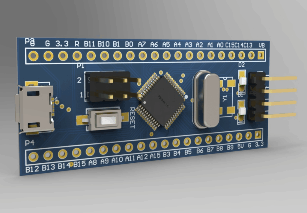
Em primeiro lugar, vamos‘Vamos falar sobre as máquinas montadoras de SMT, também chamadas de máquinas pick and place. O montador é um equipamento fundamental no processo de back-end de semicondutores. Podemos dividi-lo em duas categorias, de acordo com o tipo de montagem: A primeira é a montadora SMT: Ele pertence ao equipamento principal da linha de produção do processo de montagem em superfície. É usado principalmente para montar chips embalados, componentes eletrônicos como resistores, capacitores etc. na placa PCB. A montadora é caracterizada pela rápida velocidade de montagem, que pode chegar a 20.000 CPH e, às vezes, pode até chegar a 15.000 CPH. A precisão de montagem não é alta, geralmente entre 20 e 40μm; o segundo é o empacotador e montador avançado: É usado principalmente para a montagem de chips nus ou componentes microeletrônicos. Ele monta chips em estruturas de chumbo, dissipadores de calor, substratos ou diretamente em placas de circuito impresso. Em geral, pode ser dividido em ligação de fios e chips flip chip. Atualmente, é a principal tecnologia de conexão de embalagens de semicondutores. A colagem de fios primeiro completa a embalagem empilhada de chips por meio de uma máquina de colocação e, em seguida, conecta os pontos de almofada na parte frontal do chip às almofadas da estrutura ou do substrato por meio de uma máquina de colagem de fios. O processo atual é relativamente maduro. A montagem flip-chip é um método de colocar solda na almofada de solda na superfície do chip e soldá-la diretamente à esfera de solda correspondente no substrato após a inversão. Em comparação com a colagem com fio, ela pode alcançar maior densidade de pacote, interconexão de linha mais curta, interferência reduzida, impedância capacitiva reduzida e conexões mais estáveis e confiáveis.
Outro ponto é que os equipamentos avançados de embalagem e chip são usados principalmente na micromontagem de dispositivos lógicos, memórias, MEMS, LEDs, optoeletrônicos, RF, LD e outros dispositivos. O processo de montagem inclui C2C, C2W e W2W e pacotes 2,5D/3D. Entre elas, a embalagem 3D de alta densidade é a tendência de desenvolvimento futuro. Por meio da tecnologia through-silicon, a interconexão de chips empilhados é realizada. A característica mais óbvia da embalagem 3D de alta densidade é que ela pode reduzir o tamanho e a qualidade do produto para 1/5 a 1/10 do original. As principais tecnologias de montagem usadas incluem solda por refluxo, colagem por prensagem a quente, colagem eutética, processo adesivo, colagem ultrassônica, cura ultravioleta, processo adesivo condutor etc.
Em segundo lugar, queremos nos concentrar na tecnologia principal das máquinas SMT pick and place. O desenvolvimento de equipamentos avançados de máquinas de embalagem e montagem envolve engenharia de sistemas multidisciplinares. Os principais indicadores de desempenho do equipamento são a precisão da montagem e o rendimento da montagem. Atualmente, a maioria das máquinas de montagem atende à montagem de alta precisão ou à montagem de alto rendimento. Atender a ambos os indicadores é o desafio atual. Os principais indicadores de desempenho da máquina de montagem são afetados pelas seguintes tecnologias-chave, como sistema de alinhamento visual preciso, layout estrutural razoável, controle de movimento preciso e software de sistema completo.
A primeira tecnologia importante que queremos discutir é o sistema de contraponto visual. O sistema de alinhamento do montador passou pelo processo de alinhamento mecânico inicial, alinhamento a laser e alinhamento visual, e a precisão do alinhamento melhorou gradualmente. O sistema de alinhamento visual geralmente inclui fontes de iluminação, lentes de imagem, câmeras de conversão fotoelétrica, cartões de aquisição e software de processamento para transmissão e processamento de dados. Atualmente, o alinhamento da posição do chip e do patch de destino é realizado principalmente por meio do alinhamento visual.
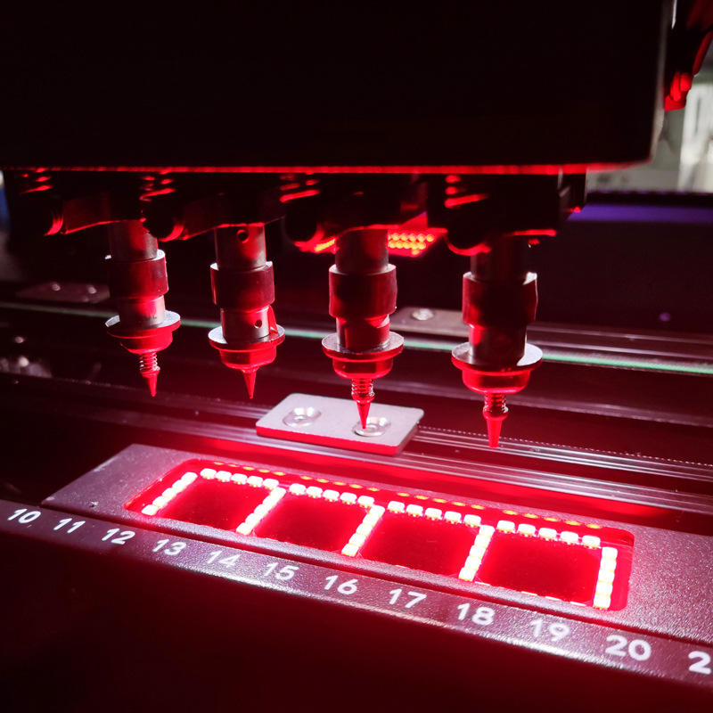
Nos equipamentos de aplicação de patches manuais e semiautomáticos, o alinhamento é realizado diretamente por meio da sobreposição de imagens. Os equipamentos de aplicação de patches totalmente automáticos usam principalmente a detecção de imagens visuais multidimensionais. Alinhamento indireto, que inclui pelo menos dois sistemas de imagem independentes. A câmera coleta imagens, extrai as bordas da imagem e identifica a posição central da imagem por meio de algoritmos de imagem. Geralmente, as câmeras de campo de visão superior e inferior são dispostas para obter, respectivamente, pontos característicos no chip ou no formato do chip e pontos característicos relacionados à posição do patch de destino, estabelecendo assim a relação de coordenadas entre o chip e os pontos de posição de destino. No processo de estabelecimento de posições de coordenadas, os métodos de alinhamento usados para a posição do patch de destino (substrato ou wafer) são divididos em alinhamento global e alinhamento local de acordo com diferentes precisões de patch. A eficiência do alinhamento global é alta. O pré-requisito para posicionar as coordenadas do bit de destino em um alinhamento é que a precisão da área da superfície do substrato ou do wafer seja alta. O alinhamento local pode se adaptar ao desvio de diferentes posições da matriz. Cada posição de patch é identificada e posicionada individualmente. É adequado para patches de alta precisão, mas, devido ao alinhamento frequente, o rendimento é relativamente baixo. A maioria dos processos de reconhecimento de imagem está em um estado estático. O reconhecimento dinâmico desenvolvido nos últimos anos tem como objetivo principal melhorar a produtividade e reduzir o tempo de espera por movimento. Ele é chamado de visão de voo. Visão de voo significa fotografia dinâmica. O sistema de visão de voo do montador precisa concluir a montagem. Quando o cabeçote de montagem se move acima da câmera de visão a uma determinada velocidade, ele coleta imagens dos componentes a serem montados pelo bocal de sucção e, ao mesmo tempo, a tecnologia de processamento de visão de alta velocidade é usada para concluir a tarefa de computação de visão.
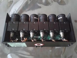
A tecnologia de visão de voo é de grande importância para melhorar a eficiência de trabalho de toda a máquina. A fotografia de voo exige a aquisição de imagens em alta velocidade, e a precisão do posicionamento é afetada pelo tempo de exposição da câmera, pelo tempo de comunicação etc. O montador que usa esse método para tirar fotos é usado principalmente em equipamentos de montagem de superfície de baixa precisão, como a precisão de montagem entre 20 e 50μm. A precisão do sistema está diretamente relacionada à resolução da câmera e da lente, bem como ao algoritmo de reconhecimento de imagem. O aprimoramento do NA da lente pode melhorar efetivamente a resolução da lente e, ao mesmo tempo, reduzir o campo de visão da lente, o que exige uma seleção equilibrada. Além disso, no caso das câmeras, o aumento da resolução da câmera também melhora os recursos de reconhecimento de imagem. O impacto negativo é aumentar a quantidade de processamento de dados de uma única imagem, aumentar o tempo de aquisição e processamento da imagem e causar impacto no rendimento. Os algoritmos de reconhecimento de imagem são muito influenciados pelo processo. O uso de diferentes algoritmos para extrair características de borda de marca pode aumentar a adaptabilidade do sistema de visão, gerando, assim, menos erros e melhorando a precisão do alinhamento.
A segunda tecnologia importante que queremos discutir é o projeto estrutural das máquinas SMT pick and place. Além do sistema de alinhamento visual preciso, o montador também deve garantir um layout estrutural razoável, um mecanismo de movimento preciso e um projeto de movimento paralelo para aumentar a produtividade. Ao mesmo tempo, ela deve garantir a estabilidade do sistema e pequenos erros de interferência ambiental. Observando o processo de evolução do montador, ele pode ser dividido em quatro tipos, de acordo com os métodos de trabalho do montador: tipo de lança, tipo de mesa giratória, tipo composto e sistema paralelo grande.
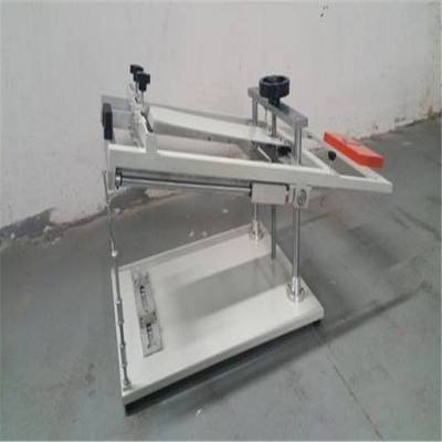
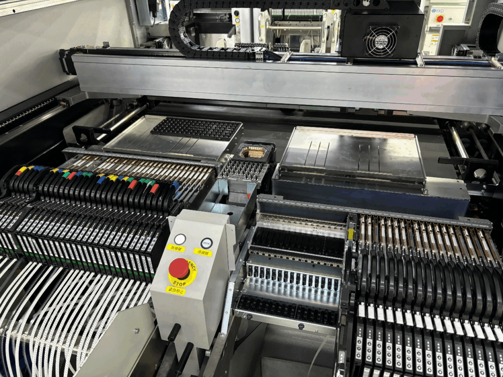
O primeiro é o tipo de braço móvel. Esse tipo de montador estrutural tem alta flexibilidade e alta precisão de montagem. Geralmente, ele é disposto em um pórtico de mármore ou fundido e é equipado com braços de montagem que se movem para frente e para trás. É a estrutura principal da maioria dos montadores. No entanto, em comparação com várias outras estruturas, os rendimentos dos adesivos são relativamente baixos, e nossos clientes da Nectec geralmente usam dois braços para melhorar os rendimentos. O segundo é o tipo de mesa giratória, que instala o cabeçote do chip em um eixo giratório. Enquanto um único cabeçote de cavacos absorve os cavacos, os cabeçotes de cavacos em outras estações podem executar ações como alinhamento e montagem, o que melhora muito a produtividade. Devido ao longo link de transmissão e à estrutura complexa, a precisão de montagem proporcionada por essa estrutura é menor do que a do tipo de braço móvel. Ela é usada principalmente em montadoras SMT, e as montadoras e embalagens avançadas ainda usam a estrutura do tipo braço móvel como peça principal. O terceiro tipo é uma estrutura composta, que pode transferir um grande número de chips de uma só vez e se concentrar na sucção e na colagem. Ela combina as vantagens de um tipo de braço móvel e de um tipo de plataforma giratória, mas a estrutura é relativamente complexa, tem altos custos de desenvolvimento e carece de flexibilidade. O quarto tipo é aquele em que os sistemas paralelos de larga escala adotam um projeto modular, e vários conjuntos de componentes de transferência ou montagem de cavacos são configurados de acordo com as estações de gargalo específicas da linha de produção para atender às necessidades de embalagem em lote das linhas de produção de larga escala.
Considerando a estabilidade da estrutura e a influência da temperatura ambiente, no projeto da estrutura do montador, tente selecionar materiais com melhor rigidez específica, ou seja, a relação entre o módulo de elasticidade e a densidade do material. Esses materiais têm boa rigidez e peso leve, como molduras de mármore e molduras de ferro fundido. O equipamento de montagem de alta precisão adiciona um sistema de amortecimento de vibração passivo ou ativo à parte inferior da estrutura para reduzir a interferência da vibração da fundação. Do ponto de vista da análise da cadeia de tamanho do erro, o coeficiente de expansão térmica do material também deve ser levado em conta. Quanto menor o coeficiente, menos o sistema de medição será afetado pela temperatura ambiente. Graças à maturidade da moderna tecnologia de simulação computadorizada, o impacto dos fatores ambientais no projeto estrutural acima pode ser otimizado por meio da análise de simulação de elementos finitos combinada com dados de teste reais, como simulação estática, simulação modal, simulação dinâmica, simulação termodinâmica etc. Em termos de melhoria da produtividade, o projeto estrutural tenta minimizar a relação entre o suprimento de material e os locais de patch de destino, encurtar o caminho e reduzir o tempo de transferência de material, pois cerca de 70% do tempo de ciclo de um único patch é usado para o manuseio de material. No projeto estrutural, o cabeçote do chip é um componente essencial do projeto estrutural. Para se adaptar ao processo de colocação de cavacos, além de atender à adsorção básica de pressão negativa do cavaco, ele também precisa atender ao nivelamento de várias liberdades para garantir o ajuste firme e uniforme do cavaco e do substrato durante o processo de colocação do cavaco. Alguns processos também exigem pressão e aquecimento para atender ao processo de colocação de cavacos eutéticos.
A terceira tecnologia importante que queremos discutir é o controle de movimento de precisão. Como há dois tipos de sistema de movimento, explicaremos cada um deles de cada vez. O primeiro sistema de movimento é o sistema de mesa esportiva. Na aplicação de máquinas avançadas de empacotamento e colocação, a fim de coordenar a transferência e a colocação de chips, plataformas de deslocamento de vários eixos são dispostas dentro do equipamento. Essas plataformas de movimento incluem os movimentos dos eixos X, Y, Z e Rz do transportador de cavacos, bem como o movimento multidimensional da cabeça do cavaco. Nos últimos anos, o mecanismo de transmissão foi gradualmente aprimorado, passando de uma estrutura de fuso de esferas acionada por servomotores e motores de passo para uma estrutura de motor de acionamento direto. Para a mesa de rolamento com cargas pesadas, um trilho-guia de flutuação de ar ou um trilho-guia maglev é usado em vez do trilho-guia de rolamento de transmissão, o que reduz a transmissão mecânica. O desgaste reduz os erros de movimento e, ao mesmo tempo, aumenta a velocidade e a aceleração da plataforma móvel, melhorando assim a produtividade do sistema. Ao aumentar a velocidade do movimento do cabeçote de cavacos, o sistema inteiro geralmente sofre impacto. No projeto do mecanismo, alguns fabricantes usam métodos como aumentar a rigidez da estrutura ou aumentar os pesos e atrair a gravidade para amortecer a força de reação do movimento e obter o equilíbrio dinâmico do sistema. O sistema tradicional de loop semifechado, como a precisão da posição de feedback do codificador, é gradualmente substituído pelo sistema de medição de régua de grade com feedback de servo de loop totalmente fechado, trazendo diretamente a precisão do chip de dezenas de mícrons para mícrons ou até mesmo precisão de montagem submicrônica.
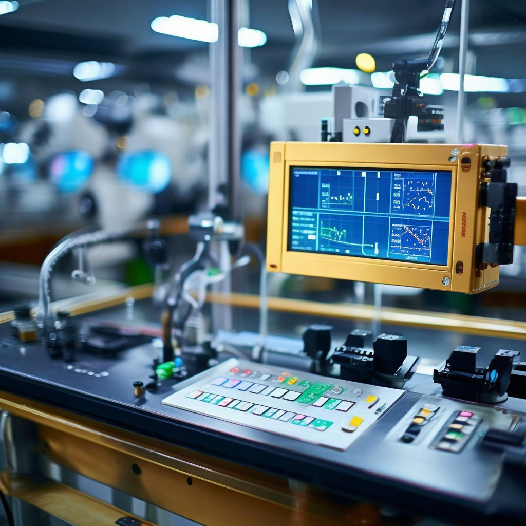
Durante o processo de acionamento da mesa de movimento, geralmente é usado o método de acionamento empilhado dos eixos X e Y. Devido à carga pesada no eixo Y na camada inferior, o trilho-guia duplo e a tecnologia de acionamento de feixe duplo podem aumentar a velocidade de movimento do eixo Y e reduzir a trepidação à esquerda e à direita. Nesse momento, os eixos de acionamento esquerdo e direito exigem sincronização rigorosa e controle de movimento síncrono. Em seguida, o segundo sistema de movimento é o sistema de controle. O sistema de controle é dividido em hardware de controle e software de controle. A arquitetura do hardware depende do módulo de controle principal. Geralmente, existem os seguintes tipos: sistema de microcomputador de chip único, sistema PLC esportivo profissional e PC mais placa de controle esportivo profissional. Entre eles, o microcomputador de chip único e o PLC são usados principalmente em equipamentos com estruturas de movimento simples e trajetórias de movimento fixas, enquanto os cartões esportivos profissionais PC plus podem realizar movimentos curvos complexos e algoritmos de movimento complexos. Para sistemas de controle complexos totalmente automáticos, um PC com placa esportiva profissional também pode ser substituído por um servidor com controlador esportivo profissional. O software do sistema é dividido em programa de controle principal do computador superior, software de interface interativa homem-computador e controle de movimento de vários eixos do computador inferior, aquisição e análise de imagens, controle de E/S, aquisição de quantidade analógica e software de calibração de precisão do sistema. Parte do aprimoramento da precisão do montador é melhorada por meio da compensação de alinhamento do sistema de visão. O computador superior geralmente é um computador industrial ou servidor, que completa a interação homem-computador, a exibição de imagens, o gerenciamento de divisão de tarefas e as funções de comunicação.
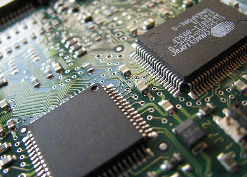
O computador inferior geralmente é um módulo de controle de movimento independente, microprocessador, PLC etc., que exige alto desempenho em tempo real e coordena vários eixos de movimento, sensores, aquisição de imagens, controle de E/S e outras ações. Para links com altos requisitos de ações em tempo real, geralmente são usados métodos de acionamento rígido para reduzir o tempo de execução do código e aumentar a produtividade.
Para concluir, à medida que os chips de CI se desenvolvem em direção à alta densidade, à alta confiabilidade e ao baixo custo no setor de circuitos integrados, são apresentados requisitos mais altos para o montador de equipamentos-chave no campo de embalagem, e a precisão e o rendimento da montagem estão aumentando a cada ano. Com o investimento contínuo no setor de circuitos integrados nos últimos anos, os fornecedores de equipamentos também enfrentarão novas oportunidades e desafios. Acreditamos que, no futuro, os equipamentos avançados de empacotamento e de chips precisarão ter características multifuncionais, modulares, flexíveis e inteligentes. Somente investindo continuamente em pesquisa e desenvolvimento de tecnologias-chave é que poderemos ser únicos na concorrência do mercado.


